1. Alignment of the OMC
A horizontal periscope (M1 and M2 mirrors) is used to have all the necessary freedom degrees. The input beam waist has to be 140 um at the center of the OMC according to the documentation (see [1] for example). An efficient procedure for the cavity alignment is to:
- Start with an incident beam roughly perpendicular to the input plane (see Fig.1)
- Center the beam in the input with M1 and center the reflection with M2 iteratively, until it is possible to see a beam at the transmission (cross or circle of points due to the multiples reflections inside the cavity).
- Continue the same process until the points are close enough to have only one point. At this step, one can observe that the reflection is no more perpendicular to the input beam, and that the transmission is not align with the input (see Fig.2)
- Finely tune the alignment with the help of cameras in reflection and transmission until it is possible to observe different modes in the transmission and the reflection of the cavity.
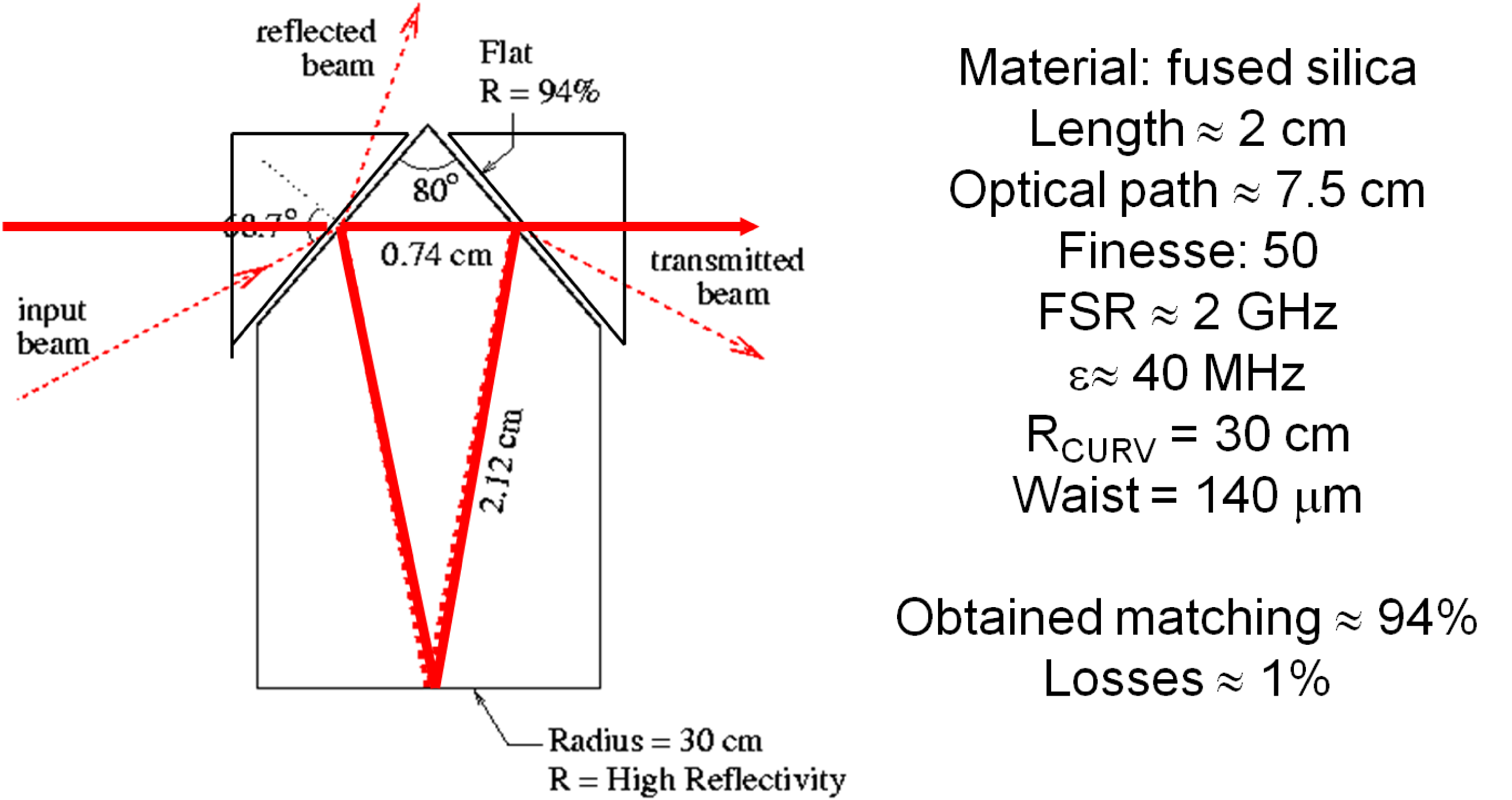
Fig.1: OMC optical layout and its main parameters [2]
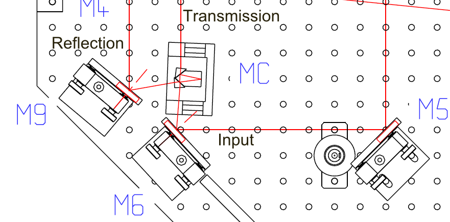
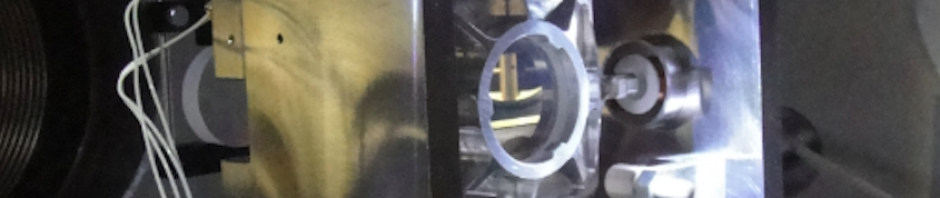
Fig.2: OMC integrated in the Virgo detection bench [1]. Please not the unusual angles when the device is properly aligned.
2. Laser lock
From this point, you will need to lock the laser frequency on the OMC cavity to improve the matching (PZT and thermal control of the laser). Here is a brief summary of the hardware in place at Calva with the references:
- 1 AOM driver (MODA80 – B4 – 34, AA Optoelectronic) generates the sidebands at 80 MHz.
- After an attenuator (PE7034-2, Pasternack Enterprises, Inc.), this reference signal (= local oscillator) is send to
- a mixer (+ 7db, + 1 db,Mini-circuits, ZP-1+) where it is mixed with the signal from the
- photodiode (PDA 10 CF EC Thorlabs) in reflection of the cavity. The output signal is then amplified and sent to the ADCs.
You should be able to scan the modes of the cavity by tuning the temperature and observe them in the transmission of the OMC with a camera. When passing the resonance, there is a PDH signal in the Laser_Sensing_PZT_pre channel.
Then follow the procedure to lock the laser (see Logbook entries 550 – 551 and 574). Please remember that due to the limited dynamic range of the PZT, you have to be very closed to the resonance to start the locking procedure. Indeed, the FSR of the OMC is about 2 GHz and the PZT tuning range is 20 times smaller with 100 MHz.
3. Mode matching improvement
In order to improve the cavity alignment and reduce the mismatching, the following procedure can be applied:
- Lock the cavity with the PDH on the TEM00
- Increase the transmitted power read with a photodiode
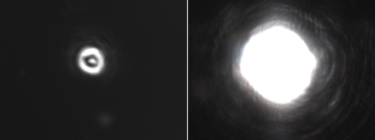
- Then decrease the mismatch (= reflected power) by playing iteratively with the periscope mirrors and the matching lens(es) while the cavity is still locked. You should see a nice Hermite-Gauss mode 11 in reflection of the cavity. For example, the reflection of the cavity seen by a Newport camera (Fig.3 a) and the OMC transmission (Fig.3 b) are presented below.
Please note that the cavity has a low finesse (F = 50). In the actual configuration, it could be difficult to reach a very high matching: there is only one lens (moving it changes the waist size and position).
(a) (b)
Fig.3: Example of a lock with 70% matching (a) Reflection of the cavity (b) Transmission of the cavity.
References:
[1] VIR-NOT-LAP-1390-264 [2] Paolo La Penna, The VIRGO detection system, January 2005, LIGO-G050017-00-R